Heads up!
You are viewing a rule from the 2023 manual. Click here to see the latest version.
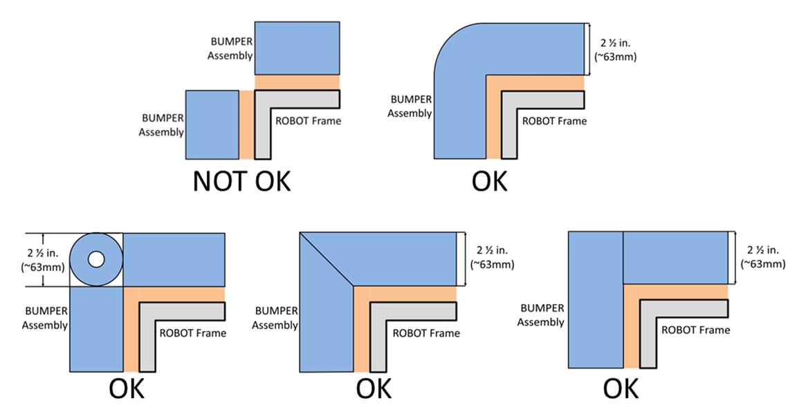
R409 *Fill Bumper corners. Corner joints between Bumpers must be filled with pool noodle material. Examples of implementation are shown in Figure 9‑8.
Figure 9‑8 Soft parts of Bumper corners
Similar Rules
Rule R401
R401
*Bumpers should protect all corners. Robots are required to use Bumpers
to protect all outside corners of the Frame Perimeter.
For adequate protection, at least 6 in. (~16 cm) of Bumper
must be placed on each side of each outside corner (see Figure 9‑3) and
must extend to within ¼ in. (~6 mm) of the Frame
Perimeter corner. If a Frame Perimeter
side is shorter than 12 in. (~31 cm), that entire FRAME PERIMETER side must be
protected by a Bumper (see Figure
9‑4). A round or circular Frame Perimeter,
or segment of the Frame Perimeter, is
considered to have an infinite number of corners, therefore the entire frame or
frame segment must be completely protected by Bumpers.
Rule R408
R408
*Bumper construction. Bumpers
must be constructed as follows (see Figure 9‑7):
Rule R410
R410
*Bumpers must be supported. Bumpers
must be supported by the structure/frame of the Robot
(see Figure 9‑9). To be considered supported, a minimum of ½ in. (~13 mm)
at each end of each Bumper wood segment must be
backed by the Frame Perimeter (≤¼ in.
gap, ~6mm). Ends exclude hard Bumper parts
which extend past the Frame Perimeter permitted
by R408-B. Additionally, any gap between the backing
material and the frame:
Rule R101
R101
*Frame Perimeter must be fixed. The Robot
(excluding Bumpers) must have a Frame Perimeter, contained within the Bumper Zone and established while in the Robots Starting
Configuration, that is comprised of fixed,
non-articulated structural elements of the Robot.
Minor protrusions no greater than ¼ in. (~6 mm) such as bolt heads, fastener
ends, weld beads, and rivets are not considered part of the Frame Perimeter.